Buying a faster station can waste capital when the next station cannot clear its output. A phased packaging line automation roadmap starts with measured losses, tests one bounded change, then releases the next capital phase against evidence from the whole line.
Plan packaging line automation in four phases: define the output requirement and current losses; stabilize the process and choose a bounded intervention; prove product handling and station interfaces; then install, measure and decide whether to expand. The sequence describes dependencies, rather than a universal investment ranking. A quality loss, unsafe manual task or obsolete control can change which intervention comes first. Keep each phase’s evidence, accountable owner and time allowance in the capital case so that an attractive machine specification cannot substitute for a workable line.
Phase 1: define the constraint before choosing equipment
Measure saleable output at one consistent line exit and identify where losses occur. Count primary packs separately from cartons or cases; note the product, pack material, format and staffing for each observation. Record when the filler is starved, when the sealer stops and when finished packs queue at case packing. A station that is waiting for product needs a different intervention from a station surrounded by blocked work.
The NIST MEP automation planning guide, chapters 1 and 3, connects automation to defined business goals, process assessment and staff preparation. Apply those principles to packaging by mapping material flow before selecting a machine. Carry the observations into the packaging line investment case, with currency amounts supplied by the plant.
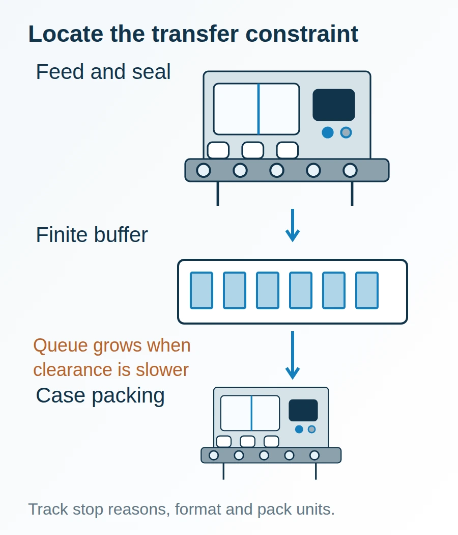
Example flow: a queue locates a transfer problem; it does not by itself establish why the downstream station is slow.
| Input or item | Typical value or source | Why it matters |
|---|---|---|
| Required good packs per shift | Plant demand plan; use one pack unit | Defines the output target |
| Available line minutes | Shift calendar less planned unavailable time | Separates demand from nameplate speed |
| Rejects and stop reasons | Time-stamped plant observations by format | Locates the loss mechanism |
| Product and packaging envelope | Approved samples and material specifications | Defines what a trial must cover |
| Downstream clearance and storage | Measured case-packing rate and usable buffer | Exposes transfer limits |
Define a baseline across the formats and operating conditions relevant to the proposal. A convenient run on an easy format cannot establish performance on a fragile product or a difficult film.
Phase 2: choose a bounded change with a release threshold
Select the intervention that addresses the recorded constraint, and state which result would justify continuing. Cleaning up a recurring transfer fault may precede a capital purchase; a hazardous task may require an earlier safety intervention. Route safety decisions through the plant’s competent assessment process.
Threshold rule: if sustained downstream good-pack clearance is below required good-pack rate under the proposed product mix, do not approve an upstream speed increase as the sole capacity solution. A finite buffer only delays blockage; it cannot remove a persistent rate deficit. Recheck the limiting station when the product mix changes.
Use an explicit demand calculation:
Required good-pack rate = required good packs ÷ (scheduled line minutes − planned unavailable minutes).
Worked example — hypothetical planning inputs: 12,000 good packs ÷ (480 − 60) minutes = 28.6 good packs/minute, rounded to one decimal place. An illustrative downstream clearance of 26 good packs/minute falls below that requirement. A machine advertised at 36 packs/minute would not resolve that downstream gap on its own.
The 420-minute window includes the operating stops and rejects that the observed effective rate must absorb; do not deduct the same stop time twice. Demand rate is a minimum planning requirement, not a machine rating or a prescribed operating margin.
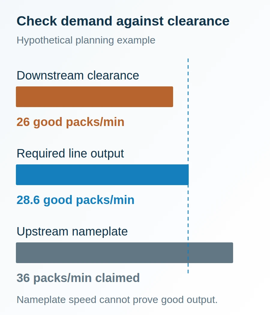
The dashed demand line tests a dependency. The upstream nameplate bar uses a different basis and cannot establish saleable output.
| Candidate intervention | Evidence that makes it relevant | Dominant Failure Mode & Prevention |
|---|---|---|
| Product feeding or orientation | Repeated starvation or misfeeds with the intended product | Product overlap at transfer; trial guides and spacing with representative samples |
| Sealing-process stabilization | Reject log ties losses to seal conditions | Product in the seal area; establish a clean product path and trial the actual pack material |
| Case packing or pallet handling | Finished packs accumulate despite stable primary packaging | Downstream blockage; validate clearance, accumulation and stop/restart signals together |
| Controls or operator support | Recovery depends on undocumented settings or fault resets | Recurrent setup errors; control recipe revisions and verify recovery instructions |
These are conditional candidates. The table does not assign a payback, savings percentage or order of financial attractiveness.
Phase 3: prove the interfaces before expanding scope
Trial the selected change with the material, formats and neighboring equipment behavior it must handle. Freeze the trial scope, counting rules, defect definitions and agreed acceptance criteria before collecting results. Include replenishment, format changes and controlled stop/restart behavior rather than observing only steady running.
Syntegon’s packaging automation overview describes connected line monitoring and a buffer that decouples upstream and downstream equipment. Those examples establish the relevance of interfaces and temporary storage. They do not establish a buffer size, staffing reduction or output guarantee for a different plant.
Specify where product waits, who owns each control signal, how a blocked station tells its neighbor to stop, and how both restart without spilling or trapping product. Record the equipment and software revisions tested. Keep items that require installed utilities or site equipment in a separate site-verification list. The equipment procurement checklist provides the broader record structure.
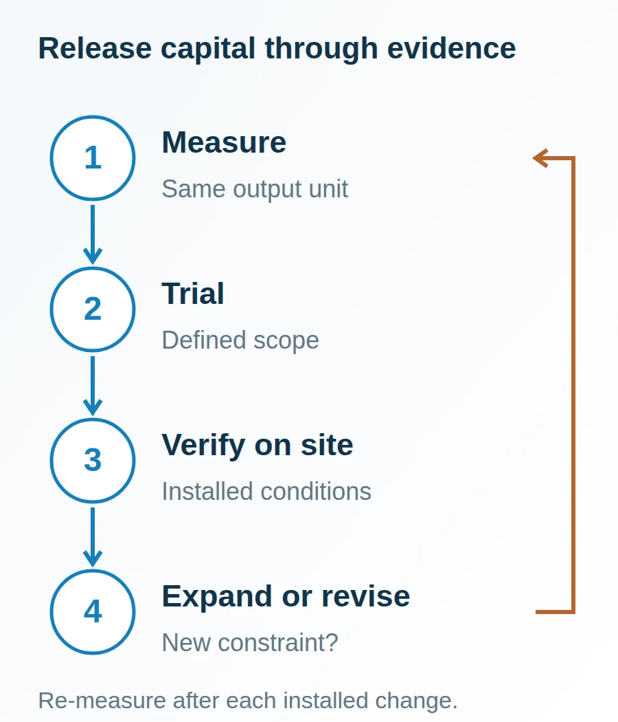
Each gate releases a decision using records; a scheduled date alone cannot close it.
Phase 4: keep a time ledger and decide whether to expand
Record people-hours, line downtime and material consumption separately before assigning costs. An installation outage, a training session and a packaging-material trial consume different resources. Concurrent activities may share calendar time while still consuming separate labor time.
| Time ledger item | Record to retain | Planning connection |
|---|---|---|
| Baseline observation | Observer-hours, formats covered and counting window | Update the investment-case inputs |
| Trial and engineering | Technician-hours, sample quantities and repeat work | Attach to the procurement records |
| Installation and recovery | Line-down minutes, restart scrap and overtime hours | Compare the scope with retrofit versus replacement |
| Training and maintenance | Operator-hours, maintenance-hours and spare-part tasks | Retain alongside the procurement handover |
| Temporary capacity cover | Outside packing time, transport and internal coordination | Check contract packing versus in-house production |
Leave time allowances unfilled until the plant and suppliers agree the work. Track film, cartons, product waste, energy and spare-part usage in their own units; apply plant-approved unit costs only in the internal capital model. Reduced handling time does not automatically become a cash saving if staffing or deployment stays the same.
After installation, compare good-pack output, rejects, changeover time and recovery behavior using the baseline definitions. Close the approved scope before proposing a further phase. If a new constraint appears, return to measurement and revise the next intervention; do not treat the original roadmap as a commitment to buy every station.
Method and sources
This roadmap is an independent capital-planning method based on NIST MEP’s process-assessment approach and the limited packaging-interface examples identified above. The sequence, release rule and time ledger are editorial planning tools. All numerical inputs in the worked example are hypothetical; they are neither measured plant results nor equipment specifications. Public sources were accessed on 19 October 2026. Last updated October 2026.